
The Objectives: |
For more details please refere to the following description. |
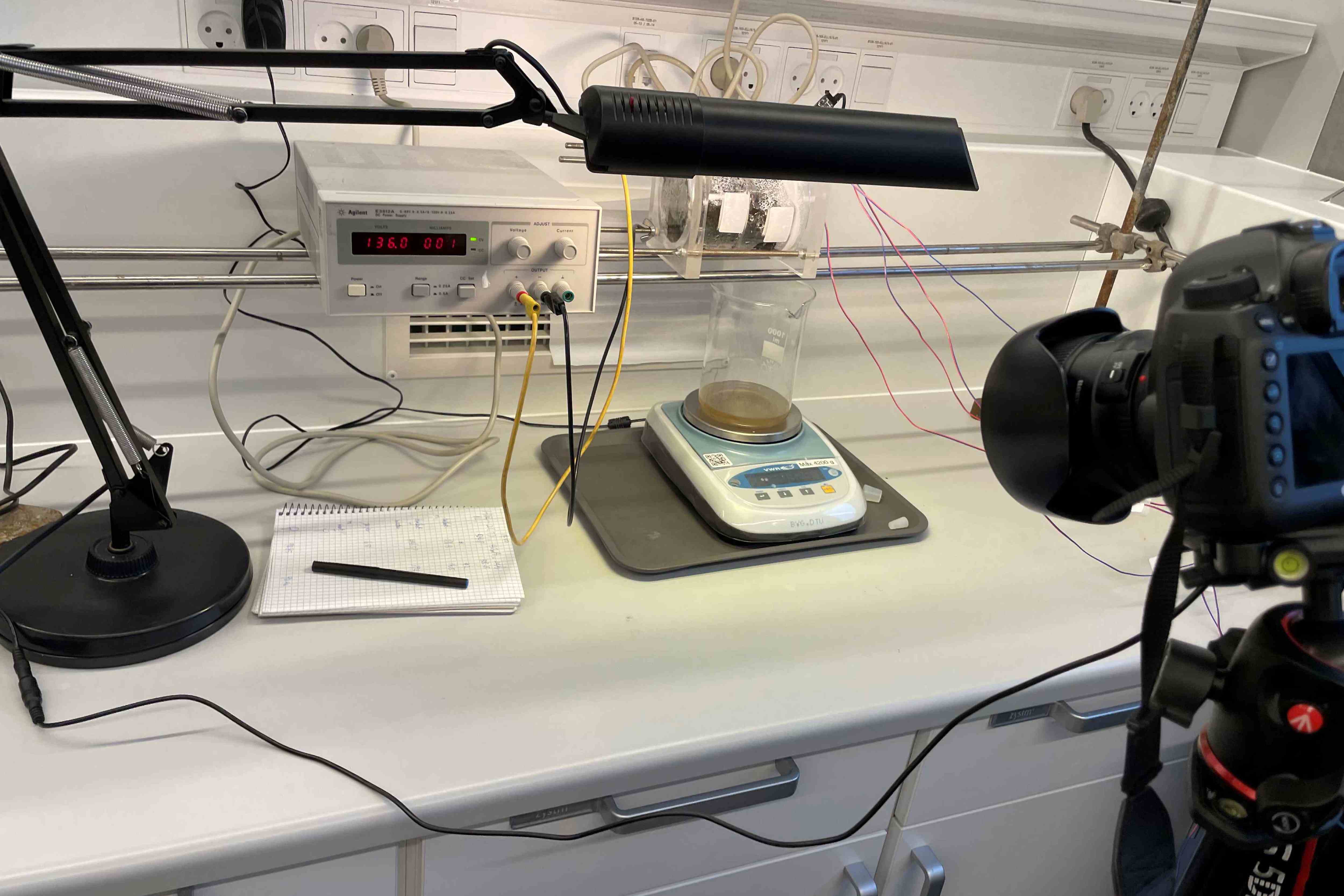
The Results: |
|
Participants: DTU (LMO), AU (AMS), AU (JM and MLC), SDU (KR)
Description
When applying an electric DC field to porous or particulate materials, interesting phenomena occur, which can be utilized in the treatment of lake sediments. Electric current is the flow of charge, and in a particulate material, this direct flow is the movement of ions dissolved in the liquid phase (electromigration). Anions will move towards the anode and cations towards the cathode. Coupled flows are the electrokinetic flows electroosmosis and electrophoresis. They are the movement of water or small charged particles, respectively. The prevailing direction for electroosmotic transport of water is from anode towards cathode, and for electrophoresis the flow of small particles will be in the opposite direction.
Electroosmotic dewatering has been tested and used to increase the dry matter content of fine soils, sediments and sludge. With the application of an electric field and compression pressure, liquid can be removed from porous, compressible materials. Further, if P is mobilized in the sediment e.g., after acidification as a result of the HTC process or the electrodialytic treatment, P will be removed with the liquid resulting in a P-rich liquid phase. Dewatering by electroosmotic (possibly combined with electrophoretic consolidation) to low water content also lowers the mass to be transported.
It is advantageous to develop a new setup with non-stationary anodes (they can be movable or there can be multiple, used at different time intervals). This is to avoid the build-up of strong gradients between the electrodes, such as gradients in pH and water content. Especially a very dry sediment around the anode would hamper further application of current, and the process will stop.
Objectives: Electroosmotic dewatering will be used to ensure dewatered sediment or HTC sludge with >60% dry matter either as a P-rich dewatered sediment or dewatered sediment with low P content. In the latter case, more than 85% of the P will be removed from the sediment.
Activities
Task 6.1: Development of lab-scale setup for dewatering by electroosmosis
A new setup with moving anodes will be designed. The idea is to avoid a gradient in water content to build between the electrodes, but instead, have a decrease in water content, which is similar all through the sediment volume. There are previous experiences at DTU to build on in this regard, but the new addition is the simultaneous mechanical consolidation and electrokinetic treatment.
Task 6.2: Electroosmotic dewatering; possibilities and limitations
Experiments based on the new setup. Determination of electroosmotic dewatering of different sediments and the residue after the HTC process to determine the optimal treatment parameters in connection to sediment/ characteristics. The P content in sediment and drained water is monitored.
Task 6.3: Upscaling to pilot scale
Laboratory scale experiments should identify operating parameters including current, voltage and compaction of materials during dewatering of dewatered sludge and HTC sludge. For the current proposed design it is hypothesized that dewatering can be undertaken in woven flexible intermediate bulk containers (FIBC), subject to change based on findings in Task 6.1 and 6.2. It is hypothesized that FIBC will be directly filled with outgoing sediment from the belt drier, electrodialysis reactor and HTC rig. The woven flexible bulk container will subsequently provide two functions (i) provide a means of storage and transportation for the sediment (it will remain in the bag until its use on the field, and the bag will enable easy handling onsite and when loading and unloading onto heavy goods vehicles (HGV) and (ii) The woven filaments will act as a filter medium, retaining the solid fraction while permitting the flow of the liquid fraction. Once filled with sediment the FIBC will be loaded onto the cathode via a forklift, with the cathode being a mesh floor on a bunded container, with the cathode providing capacity for multiple FIBC at different stages of dewatering (common negative earth). Once loaded a pronged multi-depth anode would be placed on the sediment within the FIBC, with each FIBC receiving a dedicated anode with its own dedicated charge controller, enabling dewatering efficiency to be monitored and continuous loading and unloading of samples. P (and VFA in the case of HTC) rich liquid will drain into the sump where it is pumped out and sent for P and organic acid recovery (WP3).
To enable upscaling, work will focus on (i) design and manufacture of the electro-osmotic dewatering plant and (ii) optimization of the FIBC. FIBC are customizable to the users specification, with specifications including monofilament or multifilament designs, filament density (mesh size) and material type, albeit most are polypropylene construction but natural fibers may also be available, with FICB price based on specification. Given the intended use will be as both a transport carrier and membrane, FIBC should be considered disposable, albeit some reuse may be possible. Multiple bags would need testing at different specifications and efficiency evaluated against cost. This work will predominantly be undertaken at Ormstrup.
Task 6.4 Demonstration of dewatering at Lake Ormstrup
Subject to successful pilot trials, a demonstration unit with a capacity of 8 m3 in continuous dewatering, will be constructed and tested at Lake Ormstrup alongside a bunded floor container control. The plant will be run continuously for several months to gauge usability and efficiency.
Project structure:
The work will be a collaboration between DTU and AU, with LMO leading the work at DTU and AMS leading the work at AU. Work at DTU will focus on the initial experimental validation and identification of processing parameters while AU will undertake upscaling and development of the pilot demonstration unit. Work will either be undertaken by a researcher employed at DTU and a second researcher employed at AU but equally work could be undertaken by a single PhD student working at both institutions as tasks lead simultaneously from each other.
Path to commercialization
The proposed design is deliberately intrinsically scalable and straightforward and combined with the use of IFBC provides a transport, handling and storage solution of dewatered sludge. The proposed work is ambitious, taking a technology at TRL 2-3 to TRL 6-7 within three years but also plausible. To take the system to full commercialization after this project work on automation and control would most likely be required, which would include; electric feedback loops (resistance), circuit optimization and system ergonomics, which is likely to be undertaken by a future technology provider.
Risks associated with work package
The major risk is that the process will be too impractical/ expensive in terms of energy consumption and the construction of demonstration units is not practical. Technical demonstration at lab-scale will be undertaken before the demonstration unit is constructed, and in the event that the demonstration unit is not viable work package will be ceased and funds reallocated or returned.